Free Live Webinars
Free Live Webinar: Shot Composition and Framing by Christopher Baffa, ASC
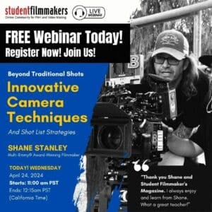
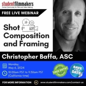
FREE Live Webinar Shot Composition and Framing Led by Christopher Baffa, ASC Webinar: “Shot Composition and Framing” Led by Christopher Baffa, ASC Date: Monday, May